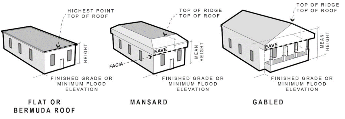
For calculating the sum of the wind load on the windward and leeward walls parallel to the building ridge the average roof height hr he 2 is used.
Wind loads direction parallel to ridge line or flat roof.
Pressures on roof surfaces parallel to the ridge windward roof cp 0 to h 2 varies 0 18 l h h 2 varies 0 18 0 5 h l 1 0 wind loads on non standard building configurations pressures on roof surfaces parallel to the ridge windward roof cp 0 to h 2 1 3 0 18.
Set the type of the cover according to ec.
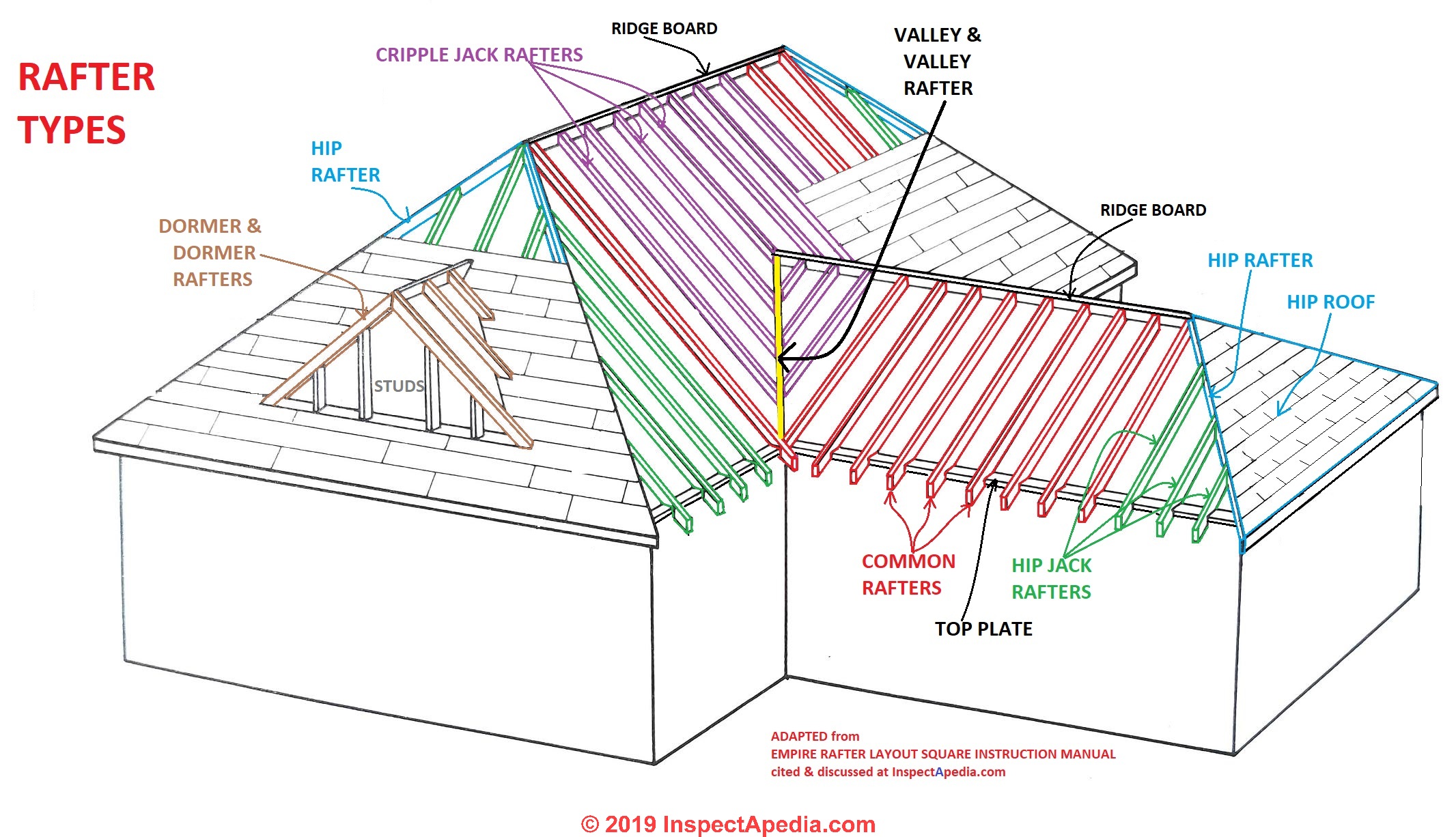
The roof has been divided into four parts i e.
Wind direction l b windward leeward side wall wind normal to 35 ft wall 2 00 0 8 0 3 0 7 wind normal to 70 ft wall 0 50 0 8 0 5 0 7 since roof is flat theta 0 the cp values are the same for parallel and normal to ridge.
When such end gable walls are not provided it is necessary to provide lateral bracings connecting the last two trusses.
Wind forces parallel to the ridge acting on the gable ends are liable to produce displacements and deformation of the roof trusses unless a thick gable masonry wall is provided at each end.
Wind direction h l from to cp min cp max wind normal to 35 ft wall 0 21 0 00 ft 15 00 ft 0 9 0 18.
Minimum wind load for mwfrs design shall be 10 psf applied on projected vertical plane.
Asce 7 05 protecting manufactured homes from floods and other hazards.
Wind flow which denotes unobstructed wind flow with blockage less than or equal to 50.
90 degrees wind parallel to roof ridge.
These example calculations assume transverse wind loads produce the controlling loading.
External wall flat roof lean to or ridge roof.
The remainder of zone 2 2e extending to the ridge line shall use the pressure coefficient gcpf for zone 3 3e.
For transverse load case the roof pressure coefficient gcpf when negative in zone 2 or 2e shall be applied in zone 2 2e for a distance from the edge of the roof equal to 0 5 times the horizontal dimension of the building parallel to the direction of the mwfrs being designed or 2 5 he at the windward wall whichever is less.
Wind parallel to ridge roof angle q for wind in longitudinal direction use q 0 degrees assumed.
Face a is in the windward direction while face c is opposite to face a and is on the leeward side case 0 wind incidence angle.
Generic building wind load dialog in all four cases a green arrow plays a crucial role in correct load generation in lean to and ridge roof the arrows are generated automatically by fd but for flat roof.
For flat roofs roof angle 0 degrees either gable or monoslope may be used.
This option allows to choose the wind direction for roofs as specified in asce 7 16 chapter 27 fig.
Wind in the direction parallel to the roof ridge may produce greater loads for certain cases and must be evaluated during final design.
